


AutoCAD 2008 User's
Guide > Work with 3D
Models > Create 3D
Models > Create 3D Solids and
Surfaces > Create Solids and
Surfaces from Lines and Curves >
Create a Solid or Surface by Lofting
With the LOFT command, you can create a 3D solid or surface by lofting (drawing a solid or surface) through a set of two or more cross-section curves.
The cross sections define the profile (shape) of the resulting solid or surface. Cross sections (generally, curves or lines) can be open (for example, an arc) or closed (for example, a circle). LOFT draws a solid or surface in the space between the cross sections. You must specify at least two cross sections when you use the LOFT command.
If you loft through a set of a closed cross-section curves, the result is a solid.
Show Me: Create a Solid by Lofting Through a Set of Cross Sections
Click the Play arrow to start the animation.
If you loft through a set of open cross-section curves, the result is a surface.
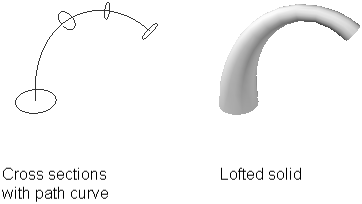
You can specify a path for the loft operation. Specifying a path gives you more control over the shape of the lofted solid or surface. It is recommended that the path curve start on the plane of the first cross section and end on the plane of the last cross section.
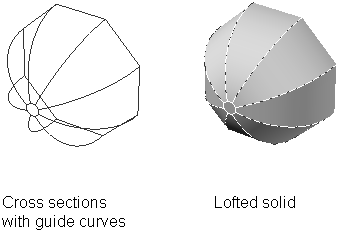
You can also specify guide curves when lofting. Guide curves are another way to control the shape of the lofted solid or surface. You can use guide curves to control how points are matched up on corresponding cross sections to prevent undesired results, such as wrinkles in the resulting solid or surface.
Each guide curve must meet the following criteria:
You can select any number of guide curves for the lofted surface or solid.
When you use only cross sections to create a lofted surface or solid, you can also use the options in the Loft Settings dialog box to control the shape of the surface or solid.
You can use the following table shows objects you can use when creating a lofted solid or surface.
|
Objects That Can Be Used as Cross Sections |
Objects That Can Be Used as a Loft Path |
Objects That Can Be Used as Guides |
|---|---|---|
|
Line |
Line |
Line |
|
Arc |
Arc |
Arc |
|
Elliptical arc |
Elliptical arc |
Elliptical arc |
|
2D polyline |
Spline |
2D spline |
|
2D spline |
Helix |
3D spline |
|
Circle |
Circle |
2D polyline |
|
Ellipse |
Ellipse |
3D polyline |
|
Points (first and last cross section only) |
2D polyline |
|
| Region |
3D polyline |
|
| Planar face of solid |
|
|
| Planar surface |
|
|
| Planar 3D face |
|
|
| 2D solid |
|
|
| Trace |
|
The DELOBJ system variable controls whether the cross sections, paths, and guides are automatically deleted when the solid or surface is created or whether you are prompted to delete the profile(s) and path.


