


AutoCAD 2008 User's
Guide > Create and Modify
Objects > Use Precision
Tools > Restrict Cursor
Movement >
Adjust Grid and Grid Snap
To enhance drawing speed and efficiency, you can display and snap to a rectangular grid. You can also control its spacing, angle, and alignment.
The grid is a rectangular pattern of dots or lines that extends over the area you specify as the grid limits. Using the grid is similar to placing a sheet of grid paper under a drawing. The grid helps you align objects and visualize the distances between them. The grid is not plotted.
Snap mode restricts the movement of the crosshairs to intervals that you define. When Snap mode is on, the cursor seems to adhere, or "snap," to an invisible rectangular grid. Snap is useful for specifying precise points with the arrow keys or the pointing device.
Grid mode and Snap mode are independent but are often turned on at the same time.
Control the Display Style and Area of the Grid
You can
display the grid either as a rectangular pattern of dots or as
rectangular pattern of lines. The grid displays dots only when the
current visual style is set to 2D Wireframe, otherwise the grid
displays lines. A lined grid is displayed for all visual styles
while working in 3D. There are several methods to change the
current visual style, including the VSCURRENT command.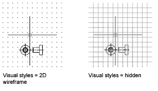
By default, the X and Y axes of the UCS display in a different color than the grid lines. You can control the color in the Drawing Window Colors dialog box. This dialog box is accessible from the Drafting tab in the Options dialog box.
The LIMITS command controls the drawing area covered by the grid. As an option, you can override the limits to make the grid cover the entire XY plane of the user coordinate system (UCS). You can access this option in the Drafting Settings dialog box or use the GRIDDISPLAY system variable.
Control the Frequency of Major Grid Lines
If the grid
is displayed as lines rather than dots, darker lines called
major grid lines display at intervals. When
working in decimal units or with feet and inches, major grid lines
are especially useful for measuring distances quickly. You can
control the frequency of major grid lines in the Drafting Settings
dialog box.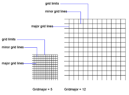
To turn off the display of major grid lines, set the frequency of major grid lines to 1.
Change the Grid Dynamically During Zooming
If you zoom in or out of your drawing, the grid spacing is adjusted automatically to be more appropriate for the new magnification. This is called adaptive grid display.
For example, if you zoom way out, the density of displayed grid lines reduces automatically. Conversely, if you zoom way in, additional grid lines display in the same proportion as the major grid lines.
As you work, you can turn Grid and Snap mode on and off, and you can change the grid and snap spacing. You can turn Snap mode on and off temporarily by using an override key.
Snap spacing does not have to match grid spacing. For example, you might set a wide grid spacing to be used as a reference but maintain a closer snap spacing for accuracy in specifying points.
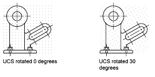
Change the Grid and Snap Angle and Base
If you need to draw along a specific alignment or angle, you can change the grid and snap angle by rotating the user coordinate system (UCS). This rotation realigns the crosshairs on the screen to match the new angle. In the following example, the UCS is rotated 30 degrees to match the angle of the anchor bracket.
The grid and snap points are always aligned with the UCS origin. If you need to shift the grid and grid snap origin, move the UCS.


