After you define a block in a drawing, you can insert a block reference in the drawing as many times as necessary. Use this method to create blocks quickly.
Each block definition includes a block name, one or more objects, the coordinate values of the base point to be used for inserting the block, and any associated attribute data.
The base point is used as a reference for positioning the block when you insert it. Suppose you specify that the base point is at the lower-left corner of an object in the block. Later, when you insert the block, you are prompted for an insertion point. The block base point is aligned at the insertion point you specified.
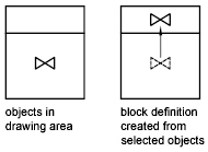
The block definition in the illustration comprises a name, PLUG_VALVE, four lines, and a base point at the intersection of the two diagonal lines. For an explanation of the schematic representation shown, see Overview of Blocks.

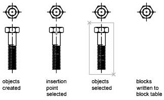
The illustration shows a typical sequence for creating a block definition within a drawing.

You can also use the Block Editor to create blocks that are saved within a drawing. For more information about using the Block Editor, see Use the Block Editor.