You can use a rectangular or polygonal clipping boundary to clip the display of a DWF underlay in a drawing.
You can define part of a DWF underlay that you want to display and plot by setting up a clipping boundary. An added advantage of setting a clipping boundary is an increase in redrawing speed because you clip only the parts of the underlay that you want visible. The clipping boundary can be a rectangle or a two-dimensional (2D) polygon with vertices within the overall extents of the underlay. Each instance of a DWF underlay can only have one clipped boundary. Multiple instances of the same underlay can have different boundaries. You can change the boundary of a clipped underlay at any time.
You can display a clipped underlay using the clipping boundary, or you can hide the clipping boundary to display the underlay with its original boundaries.
When the clipping boundary is no longer needed, you can delete the clipped boundary from the underlay. When you delete a clipping boundary, the underlay is displayed with its original boundary.
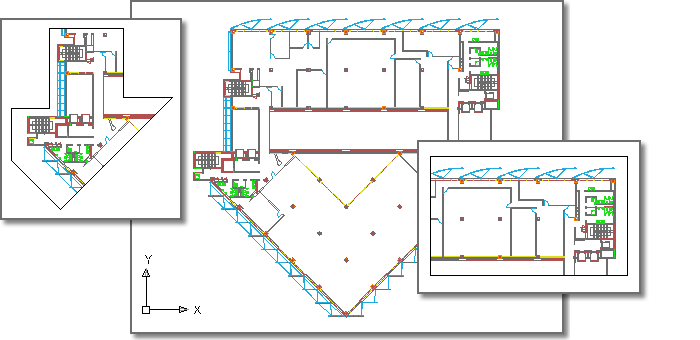
Following is an example of a DWF underlay with insets showing polygonal (l) and rectangular (r) clipping boundaries: