


AutoCAD 2008 User's
Guide > Create Realistic
Images and Graphics > Render 3D Objects
for Realism > Prepare a Model for
Rendering >
Minimize Intersecting and Coplanar Faces
Certain kinds of geometry create special rendering problems.
The complexity of an object relates to the number of its vertices and faces. The more faces a model has, the longer it takes to render. Keep the geometry of your drawing simple to keep rendering time to a minimum. Use the fewest faces possible to describe a surface.
Intersecting faces in a model occur when two objects pass through one other. For conceptual design situations, simply placing one object through another is a fast way to visualize how something will look. However, the edge created where the two objects intersect can exhibit a rippled appearance.
In the following example, the edge appears rippled in the left image and much cleaner after a Boolean union.
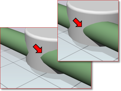
When edges do not appear to be as precise as you want, use Boolean operations like union, intersect, and subtract. A much cleaner and precise edge is created to better reflect the object’s appearance.
Faces that overlap and lie in the same plane, coplanar faces, can produce ambiguous results, especially if the materials applied to the two faces differ.
In the following example, artifacts appear when faces occupy the same location.
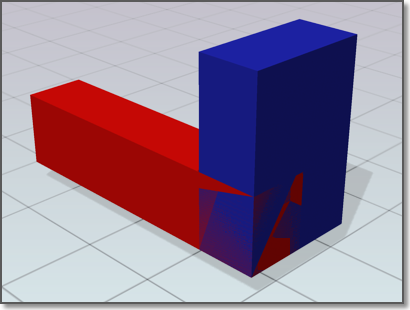
Moving an object so its faces no longer occupy the same plane as another object will fix this situation.
Faces that self-overlap due to a 180-degree twist can also produce ambiguous results, because the normal for the face is not well defined.
In the following example, artifacts appear where the face is twisted due to crossing the second and thirds corner points.
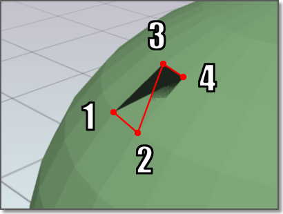
This situation is often encountered when trying to fix a model that has a hole in its surface. For example, when corner points are selected for the new face, the points are crossed instead of being placed around the hole in a counter-clockwise direction. Avoid this problem by choosing corner point in the proper order.


