


AutoLISP
Developer's Guide > Using the AutoLISP
Language > Using AutoLISP to
Communicate with AutoCAD > Device Access and
Control >
Calibrating Tablets
AutoCAD users can calibrate a digitizing tablet by using the TABLET command (see the Command Reference for a description of this command). The tablet function enables applications to manage calibration by setting the calibrations directly and by saving those settings for future use.
The first argument to the tablet function is an integer code. If code is equal to 0, the function returns the current calibration. If code is equal to 1, the calibration is set according to the remaining arguments. Calibrations are expressed as four 3D points (in addition to the code). The first three points—row1, row2, and row3—are the three rows of the tablet's transformation matrix. The fourth point, direction, is a vector that is normal to the plane in which the tablet's surface is assumed to lie (expressed in WCS, the World Coordinate System). When the calibration is set with the TABLET command, the tablet's surface is assumed to lie in the XY plane of the current UCS.
The following sample routine retrieves the current tablet calibration and stores it in the variable tcal:
(defun C:TABGET ( )
(setq tcal (tablet 0))
(if tcal
(princ
(strcat "\nConfiguration saved, "
"use TABSET to retrieve calibration.")
)
(princ "\nCalibration not obtainable ")
)
(princ)
)
If the preceding routine was successful, the symbol tcal now contains the list returned by the tablet function. This list might appear as follows:
(1 (0.00561717 -0.000978942 -7.5171)
(0.000978942 0.00561717 -9.17308)
(0.0 0.0 1.0)
(0.0 0.0 1.0)
)
To reset the calibration to the values retrieved by the preceding routine, you can use the C:TABSET routine, as follows:
(defun C:TABSET ( )
(if (not (apply 'tablet tcal))
(princ "\nUnable to reset calibration. ")
(progn
(princ "\nTablet calibration reset. ")
(setvar "tabmode" 1)
(if (= (getvar "tabmode") 0)
(princ "\nUnable to turn on tablet mode ")
)
)
)
(princ)
)
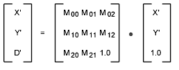
The transformation matrix passed as row1, row2, and row3 is a 3W3 transformation matrix that is meant to transform a 2D point. The 2D point is expressed as a column vector in homogeneous coordinates (by appending 1.0 as the third element), so the transformation looks like this:
The calculation of a point is similar to the 3D case. AutoCAD transforms the point by using the following formulas:
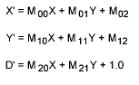
To turn the resulting vector back into a 2D point, the first two components are divided by the third component (the scale factor D') yielding the point (X'/D',Y'/D').
For projective transformations, the most general case, tablet does the full calculation. But for affine and orthogonal transformations, M20 and M21 are both 0, so D' would be 1.0. The calculation of D' and the division are omitted; the resulting 2D point is simply (X',Y').
As the previous paragraph implies, an affine transformation is a special, uniform case of a projective transformation. An orthogonal transformation is a special case of an affine transformation: not only are M20 and M21 zero, but M00 = M11 and M10 = -M01.