The following group codes apply to angular dimensions. In addition to the group codes described here, those listed in Common Group Codes for Entities and Common Dimension Group Codes can also be present. For information about abbreviations and formatting used in this table, see Formatting Conventions in This Reference.
|
Angular dimension group codes |
|
|---|---|
|
Group code |
Description |
|
100 |
Subclass marker (AcDb3PointAngularDimension) |
|
13 |
Definition point for linear and angular dimensions (in WCS) DXF: X value; APP: 3D point |
|
23, 33 |
DXF: Y and Z values of definition point for linear and angular dimensions (in WCS) |
|
14 |
Definition point for linear and angular dimensions (in WCS) DXF: X value; APP: 3D point |
|
24, 34 |
DXF: Y and Z values of definition point for linear and angular dimensions (in WCS) |
|
15 |
Definition point for diameter, radius, and angular dimensions (in WCS) DXF: X value; APP: 3D point |
|
25, 35 |
DXF: Y and Z values of definition point for diameter, radius, and angular dimensions (in WCS) |
|
16 |
Point defining dimension arc for angular dimensions (in OCS) DXF: X value; APP: 3D point |
|
26, 36 |
DXF: Y and Z values of point defining dimension arc for angular dimensions (in OCS) |
The points (13,23,33) and (14,24,34) specify the endpoints of the line used to determine the first extension line. Points (10,20,30) and (15,25,35) specify the endpoints of the line used to determine the second extension line. Point (16,26,36) specifies the location of the dimension line arc. The point (11,21,31) specifies the midpoint of the dimension text.
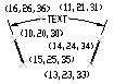
The point (15,25,35) specifies the vertex of the angle. The points (13,23,33) and (14,24,34) specify the endpoints of the extension lines. The point (10,20,30) specifies the location of the dimension line arc and the point (11,21,31) specifies the midpoint of the dimension text.


