Developing an
AutoLISP program begins with an idea for automating some aspect of
AutoCAD.. It may be a need to speed up a repetitive
drafting function, or to simplify a complex series of operations.
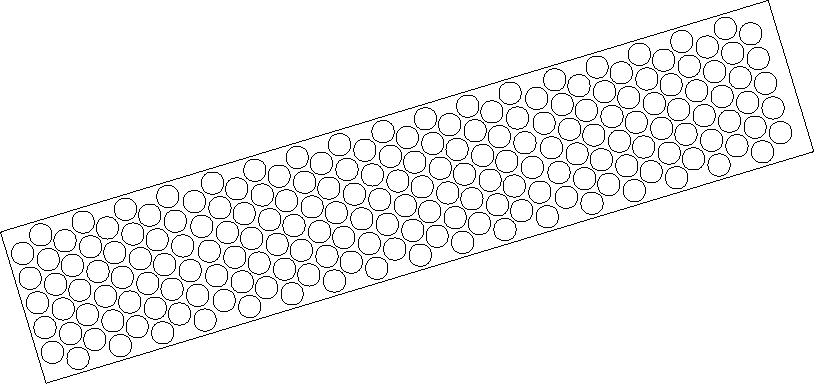
For the tutorial, the garden path you want your program to draw is
a complex shape with a variable number of components, based on
initial input from the user. Here's what it will look like:
Your program
must do the following to draw the garden path:
Given a start point, an endpoint, and a width, draw a
rectilinear boundary. The boundary can be at any 2D orientation.
There should be no limit on how large or small it can be.
Prompt the user for tile size and tile spacing values. The
tiles are simple circles and will fill the boundary but must not
overlap or cross the boundary.
Place the tiles in alternating rows.
To see how
things should work, you can run a completed version of the
application that is supplied with AutoCAD.
To run the
supplied example
From the AutoCAD Tools menu, choose Load Application.
Select gardenpath.vlx from the Tutorial\VisualLISP directory, and choose Load.
Choose Close.
At the Command prompt, enter gpath.
Respond to the first two prompts by picking a start point and
an endpoint in the AutoCAD drawing area.
Enter 2 at the half-width of Path
prompt.
Choose OK when prompted by the Garden Path Tile Specifications
dialog box.